VAO는 Vertex Array Object의 약자로써 Object 속성을 바인딩하여 쉽게 사용할 수 있도록 한다.
본 페이지에서는 정육면체를 기준으로 설명한다.
Vertex 좌표(position), Texture coordinates (UV), Index 데이터를 이용한 VAO의 생성은 아래 순서와 같다.
- VAO 생성
- Attribute에 Vertex 좌표, Texture coordinates 전달
- 버퍼에 Index 저장
- VAO 바인딩 해제
1. VAO 생성

GL30.glGenVertexArrays() 함수를 호출하여 VAO ID를 생성한다.
생성한 VAO는 GL30.glBindVertexArray() 함수를 호출하여 바인딩 한다.
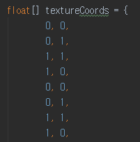
2. Attribute에 Vertex 좌표, Texture coordinates 전달

Vertex Shader에 선언한 변수(vec3 position, vec2 textureCoords)에 데이터를 전달하기 위해 storeDataInAttributeList() 함수를 사용한다.
storeDataInAttributeList() 함수 내에서는 크게 아래와 같은 순서로 진행된다.
- VBO (Vertex Buffer Object) 생성
- VBO 바인딩
- 데이터 행렬을 Buffer로 변환
- VBO에 데이터 입력
- Shader의 Attribute 와 연결
- VBO 언바인딩
[1-2]. VBO 생성 및 바인딩
GL15.glGenBuffers() 함수를 호출하여 VBO ID를 생성한다.
GL15.glBindBuffer() 함수를 호출하여 VBO를 바인딩 할 수 있으며,
Attribute를 넣기 위해 파라미터로 GL15.GL_ARRAY_BUFFER와 VBO ID를 넣는다.
[3]. 데이터 행렬을 Buffer로 변환
데이터를 전달하기 전에 Java에서는 Buffer로 데이터를 전환하며,
storeDataInFloatBuffer() 함수를 사용한다.

[4-5]. VBO 데이터 입력 및 Attribute와 연결

GL15.glBufferData() 함수를 사용하여 생성한 데이터 버퍼를 바인딩한다.
파라미터로는 GL15.GL_ARRAY_BUFFER, Buffer, GL15.GL_STATIC_DRAW를 넣는다.
GL_ARRAY_BUFFER 는 버퍼의 타겟이며, GL_STATIC_DRAW는 버퍼의 데이터가 변하는 것인지(Dynamic) 아니면 정적인 데이터인지(Static)를 나타낸다.
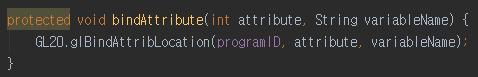
버퍼 바인딩 후, GL20.glVertexAttribPointer() 함수를 사용하여 Shader의 Attribute에 연결시킨다. 파라미터로는 Shader 생성 시 Attribute name과 Bind한 Location handler, 데이터 셋의 크기, 데이터 형식, 정규화 여부, stride, offset을 입력하며 자세한 설명은 http://blog.daechan.net/2018/03/513.html 를 참조한다.
위의 과정을 통해 VBO를 생성하고 데이터를 저장한 후 Shader의 Attribute로 전달할 수 있게 되었다.
[6]. VBO 언바인딩
GL15.glBindBuffer(0)함수를 호출하여 0번 VBO를 바인딩 함으로써, 설정을 완료한 VBO를 Unbind 한다.
3. 버퍼에 Index 저장

bindIndicesBuffer() 함수를 사용하여 Index 데이터를 Buffer에 바인딩한다.
순서는 위의 storeDataInAttributeList() 함수와 동일하며,
차이점으로는 버퍼의 타겟을 GL15.GL_ELEMENT_ARRAY_BUFFER 로 설정한다.
glBufferData() 함수에 대한 Khronos 문서를 참조하면 아래와 같다. 자세한 설명은 http://blog.daechan.net/2018/03/chapter-51.html를 참조한다.
 |
| https://www.khronos.org/registry/OpenGL-Refpages/gl4/html/glBufferData.xhtml |
4. VAO 바인딩 해제
GL30.glBindVertexArray(0) 함수를 호출하여 0번 VAO를 Bind 함으로써 VAO 바인딩을 해제한다.
0번 VAO를 Bind할 때의 동작에 대한 설명은 Khronos 문서에 아래와 같이 설명되어 있다.
"
glBindVertexArray binds the vertex array object with name array. array is the name of a vertex array object previously returned from a call to glGenVertexArrays, or zero to break the existing vertex array object binding."(https://www.khronos.org/registry/OpenGL-Refpages/gl4/html/glBindVertexArray.xhtml)