2019년 3월 25일 월요일

VAO, VBO 만들기 정리

Vertex 좌표, Texture coordinates (UV), Index를 가지고 VAO를 만들 수 있다.
VAO는 Vertex Array Object의 약자로써 Object 속성을 바인딩하여 쉽게 사용할 수 있도록 한다.
본 페이지에서는 정육면체를 기준으로 설명한다.

Vertex 좌표(position), Texture coordinates (UV), Index 데이터를 이용한 VAO의 생성은 아래 순서와 같다.

  1. VAO 생성
  2. Attribute에 Vertex 좌표, Texture coordinates 전달
  3. 버퍼에 Index 저장
  4. VAO 바인딩 해제


1. VAO 생성


GL30.glGenVertexArrays() 함수를 호출하여 VAO ID를 생성한다.
생성한 VAO는 GL30.glBindVertexArray() 함수를 호출하여 바인딩 한다.


2. Attribute에 Vertex 좌표, Texture coordinates 전달


Vertex Shader에 선언한 변수(vec3 position, vec2 textureCoords)에 데이터를 전달하기 위해 storeDataInAttributeList() 함수를 사용한다.
storeDataInAttributeList() 함수 내에서는 크게 아래와 같은 순서로 진행된다.

  1. VBO (Vertex Buffer Object) 생성
  2. VBO 바인딩
  3. 데이터 행렬을 Buffer로 변환
  4. VBO에 데이터 입력
  5. Shader의 Attribute 와 연결
  6. VBO 언바인딩


[1-2]. VBO 생성 및 바인딩
GL15.glGenBuffers() 함수를 호출하여 VBO ID를 생성한다.
GL15.glBindBuffer() 함수를 호출하여 VBO를 바인딩 할 수 있으며,
Attribute를 넣기 위해 파라미터로 GL15.GL_ARRAY_BUFFER와 VBO ID를 넣는다.

[3]. 데이터 행렬을 Buffer로 변환
데이터를 전달하기 전에 Java에서는 Buffer로 데이터를 전환하며,
storeDataInFloatBuffer() 함수를 사용한다.


[4-5]. VBO 데이터 입력 및 Attribute와 연결


GL15.glBufferData() 함수를 사용하여 생성한 데이터 버퍼를 바인딩한다.
파라미터로는 GL15.GL_ARRAY_BUFFER, Buffer, GL15.GL_STATIC_DRAW를 넣는다.
GL_ARRAY_BUFFER 는 버퍼의 타겟이며, GL_STATIC_DRAW는 버퍼의 데이터가 변하는 것인지(Dynamic) 아니면 정적인 데이터인지(Static)를 나타낸다.

버퍼 바인딩 후, GL20.glVertexAttribPointer() 함수를 사용하여 Shader의 Attribute에 연결시킨다. 파라미터로는 Shader 생성 시 Attribute name과 Bind한 Location handler, 데이터 셋의 크기, 데이터 형식, 정규화 여부, stride, offset을 입력하며 자세한 설명은 http://blog.daechan.net/2018/03/513.html 를 참조한다.

위의 과정을 통해 VBO를 생성하고 데이터를 저장한 후 Shader의 Attribute로 전달할 수 있게 되었다.

[6]. VBO 언바인딩
GL15.glBindBuffer(0)함수를 호출하여 0번 VBO를 바인딩 함으로써, 설정을 완료한 VBO를 Unbind 한다.


3. 버퍼에 Index 저장


bindIndicesBuffer() 함수를 사용하여 Index 데이터를 Buffer에 바인딩한다.
순서는 위의 storeDataInAttributeList() 함수와 동일하며,
차이점으로는 버퍼의 타겟을 GL15.GL_ELEMENT_ARRAY_BUFFER 로 설정한다.
glBufferData() 함수에 대한 Khronos 문서를 참조하면 아래와 같다. 자세한 설명은 http://blog.daechan.net/2018/03/chapter-51.html를 참조한다.

https://www.khronos.org/registry/OpenGL-Refpages/gl4/html/glBufferData.xhtml

4. VAO 바인딩 해제

GL30.glBindVertexArray(0) 함수를 호출하여 0번 VAO를 Bind 함으로써 VAO 바인딩을 해제한다.
0번 VAO를 Bind할 때의 동작에 대한 설명은 Khronos 문서에 아래와 같이 설명되어 있다.

"glBindVertexArray binds the vertex array object with name arrayarray is the name of a vertex array object previously returned from a call to glGenVertexArrays, or zero to break the existing vertex array object binding."
(https://www.khronos.org/registry/OpenGL-Refpages/gl4/html/glBindVertexArray.xhtml)


2019년 3월 20일 수요일

Vertex, Texture Coordinate(UV), Index 정리

Vertex 좌표, Texture Coordinates (UV), Index를 가지고 VAO를 만들 수 있다.
VAO는 Vertex Array Object의 약자로써 Object 속성을 바인딩하여 쉽게 사용할 수 있도록 한다.
본 페이지에서는 정육면체를 기준으로 설명한다.

1. Vertex


정육면체의 각 면을 구성하는 좌표들로 구성한다.
한 면의 vertex 수 (4) * 면의 수(6) = 24개의 (x, y, z) 좌표로 이루어져 있다.
처음 4개의 정점을 보면 z좌표가 -0.5로써 정육면체의 바닥을 나타냄을 알 수 있다.

바닥 면의 정점 좌표 그래프

2. Texture Coordinate (UV)


위의 각 Vertex 마다 Texture의 어느 부분에 해당하는지 나타낸다.
UV 범위는 0~1로써, U는 Texture의 X 좌표이고 V는 Texture의 Y 좌표이다.
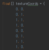
데이터는 위의 Vertex 데이터 수와 동일하게 24개의 (u, v) 좌표로 이루어져 있다.
처음 4개의 정점은 (0, 0) - (0, 1) - (1, 1) - (1, 0)으로 바닥 면에 Texture 전체를 매핑한다.

3. Index


Index는 정육면체를 어떻게 그릴 것인지를 나타낸다.
정육면체의 각 면은 삼각형 2개로 분할하여 그리므로
면의 수(6) * 면 당 삼각형의 수(2) = 12개의 데이터셋으로 구성되며
각 데이터셋은 vertex index 3개로 구성된다.
위에서의 Vertex 수는 24개 이므로 index의 범위는 0 부터 23 까지이다.


2019년 3월 19일 화요일

셰이더 프로그램 만들기 정리

셰이더 프로그램을 만드는 방법은 크게 아래와 같은 순서로 진행된다.

  1. Create Vertex Shader
  2. Create Fragment Shader
  3. Create Program
  4. Attach Shaders to Program
  5. Link Program
  6. Validate Program
  7. Bind Attributes
  8. Get Uniform Locations

1. Create Vertex and Fragment Shader [1-2]


loadShader() 함수를 통해 Handler 성격의 각 Shader id 가 생성된다.
loadShader() 함수 내부의 순서는 다음과 같다.
  1. Shader가 저장 된 txt 파일을 읽어 String 형식으로 변환.
  2. GL20.glCreateShader() 함수를 호출하여 Shader 생성.
    Shader type를 파라미터로 넣는다. (GL20.GL_VERTEX_SHADER, GL20.GL_FRAGMENT_SHADER)
  3. Shader ID에 위에서 불러온 Shader string을 설정(Shader source).
  4. GL20.glCompileShader() 함수로 Shader ID를 전달하여 Compile.


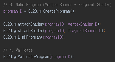
2. Create Program [3, 4, 5, 6]

생성한 Shader를 바탕으로 Program을 생성한다.
프로그램의 생성 순서는 다음과 같다.
  1. GL20.glCreateProgram() 함수를 호출하여, Program 생성.
  2. GL20.glAttachShader() 함수를 호출하여, Program과 생성한 Shader들을 Attach 시킨다.
  3. GL20.glLinkProgram() 함수를 호출하여, Program과 Shader들을 Link 시킨다.
  4. GL20.glValidateProgram() 함수로 Program을 검증한다.


3. Bind Attributes [7]

Shader 내의 변수를 Attribute ID로 Bind 시킨다.
예를들어, Vertex Shader 내의 "vec3 position" 변수나 "vec2 textureCoords" 변수 등에 접근하기 위해 매번 찾지 않고 Attribute ID로 빠르게 접근할 수 있다.


위와 같이 attribute id와 변수명을 bind 한다. super.bindAttribute() 함수 내에서는


GL20.glBindAttribLocation() 함수를 사용하여 Program에서 attribute id와 변수명을 연결시킨다.

4. Get Uniform Locations [8]

Shader 내의 Uniform 변수에 접근하기 위해 Handler 성격의 Integer id를 불러온다.
위와 동일하게 handler로 접근함으로써 빠른 데이터의 적재가 가능하다.


위의 그림에서와 같이 Program에서 Uniform 변수 명으로 변수 위치를 불러와 전역변수로 저장한다.


getUniformLocation() 함수 내에서는 GL20.glGetUniformLocation() 함수로 Program에서 Uniform 변수 명으로 변수 위치를 불러와 리턴한다.


2018년 7월 31일 화요일

5.5.5-[3, 4] 밉맵(Mipmap), 밉맵 필터링


  1. 렌더링 성능과 퀄리티를 높이는 텍스쳐 기법
  2. 기존 밉맵을 사용하지 않을 때의 문제점
    1. 반짝거림 현상
      1. 렌더링 크기가 텍스쳐 크기보다 작은 경우. 
      2. 성능
  3. 밉맵이란?
    1. 여러 크기의 밉맵 텍스쳐를 준비하고, 현재에 가장 적합한 텍스쳐를 선택하는 기법
  4. 초기 설정
    1. glTexSubImage2D
      1. void glTexSubImage2D(GLenum target,
        GLint level,
        GLint xoffset,
        GLint yoffset,
        GLsizei width,
        GLsizei height,
        GLenum format,
        GLenum type,
        const GLvoid * data);
        1. level
          1. 0, 1, 2 ~ 순
          2. 밉맵을 사용하지 않을 경우 0으로 설정
  5. 밉맵 기본 레벨 및 최대 레벨 지정
    1. glTexParameteri
      1. void glTexParameteri(GLenum target,
        GLenum pname,
        GLint param);
    2. 예제
      1. // 기본 레벨을 0으로
      2. glTexParameteri(GL_TEXTURE_2D, GL_TEXTURE_BASE_LEVEL, 0);

      3. // 최대 레벨을 4로
      4. glTexParameteri(GL_TEXTURE_2D, GL_TEXTURE_MAX_LEVEL, 4);
  6. 밉맵 필터링
    1. 텍스쳐 필터링의 종류
      1. GL_NEAREST
        Returns the value of the texture element that is nearest (in Manhattan distance) to the center of the pixel being textured.
        GL_LINEAR
        Returns the weighted average of the four texture elements that are closest to the center of the pixel being textured.
        GL_NEAREST_MIPMAP_NEAREST
        Chooses the mipmap that most closely matches the size of the pixel being textured and uses the GL_NEAREST criterion (the texture element nearest to the center of the pixel) to produce a texture value.
        GL_LINEAR_MIPMAP_NEAREST
        Chooses the mipmap that most closely matches the size of the pixel being textured and uses the GL_LINEAR criterion (a weighted average of the four texture elements that are closest to the center of the pixel) to produce a texture value.
        GL_NEAREST_MIPMAP_LINEAR
        Chooses the two mipmaps that most closely match the size of the pixel being textured and uses the GL_NEAREST criterion (the texture element nearest to the center of the pixel) to produce a texture value from each mipmap. The final texture value is a weighted average of those two values.
        GL_LINEAR_MIPMAP_LINEAR
        Chooses the two mipmaps that most closely match the size of the pixel being textured and uses the GL_LINEAR criterion (a weighted average of the four texture elements that are closest to the center of the pixel) to produce a texture value from each mipmap. The final texture value is a weighted average of those two values.
      2. https://www.khronos.org/registry/OpenGL-Refpages/es2.0/xhtml/glTexParameter.xml
    2. GL_LINEAR나 GL_NEAREST로 설정하는 경우 밉맵을 사용하지 않는다.
    3. GL_NEAREST_MIPMAP_NEAREST는 성능이 좋고 Aliasing이 적다.
    4. GL_LINEAR_MIPMAP_NEAREST가 일반적으로 게임에서 많이 사용되는데,
      더 좋은 필터링 결과와 다른 크기의 맵 레발 간에 밉맵선택이 빠르기 때문.
    5. 위의 GL_*_MIPMAP_* GL_TEXTURE_MIN_FILTER에만 적용이 가능하다.
      GL_TEXTURE_MAG_FILTER는 GL_LINEAR 또는 GL_NEAREST여야 한다.
    6. Nearest 방식은 밉 레벨이 바뀌는 부분에 일그러진 구간이 보일 수 있으며, 이는 GL_LINEAR_MIPMAP_LINEAR 또는 GL_NEAREST_MIPMAP_LINEAR로 해결할 수 있으나, 추가 연산으로 오버헤드가 발생한다.
    7. GL_LINEAR_MIPMAP_LINEAR는 삼중선형 밉맵이라고도 하며 좋은 결과를 나타낸다.